
 After success full implementation of serial programmer, I turned to make a USBasp programmer .The firmware is downloaded from USBasp official site.In this tutorial we will see how to use AVRdude for burning hex files into AVR microcontroller using USBasp. USBasp is a USB in-circuit programmer for Atmel AVR controllers. It simply consists of an ATMega8 and a couple of passive components. The programmer uses a firmware-only USB driver, no special USB controller is needed. In my circuit only use the six pins(MOSI,MISO,SCK,RESET,GND,+5V) from the usbasp to target microcontroller, It is little different from actual circuit in official site. No need of external +5V power supply to target microcontroller. The circuit is given below
 |
| USBasp programmer |
NOTE:The fuse bits for 12Mhz crystal HFUSE=0xc9 and LFUSE=0xef burn explicitly to atmega8 using serial programmer(any programmer).It is very important, the USBasp programmer cannot work with default fuse bits. The command for setting the fuse bit:
avrdude -c ponyser -p m8 -P /dev/ttyS0 -U lfuse:w:0xc9:m -U hfuse:w:0xef:m
For reading the current fuse bit in atmega8:
avrdude -c ponyser -p m8 -P /dev/ttyS0 -U hfuse:r:high.bin:b -U lfuse:r:low.bin:b
Then cat the high.bin and low.bin gives the output in binary

After setting the fuse bit, download the tar file from USBasp site and extract it. Then burn the firmware usbasp.atmega8.xxxx-xx-xx.hex contains in the folder '/bin/firmware/' to atmega8 using the serial programmer and put it in above usbasp circuit. Connect the USBasp programmer to USB port of PC and type the command lsusb in terminal under linux(Ububtu 12.04 ). It gives an out put like this
Bus 005 Device 002: ID 16c0:05dc VOTI shared ID for use with libusb
or
Bus 005 Device 002: ID 16c0:05dc USBasp programmer
USBasp PROGRAMMER TESTING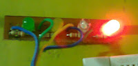
Use the hex file ledblink.hex in my previous post to burn first program using USBasp to another atmega8(target).Connect the USBasp to target microcontroller. The USBasp to target microcontroller(it vary for different AVR microcontroller, please refer the data sheets) connection circuit with LED is below:

Use the hex file ledblink.hex in my previous post to burn first program using USBasp to another atmega8(target).Connect the USBasp to target microcontroller. The USBasp to target microcontroller(it vary for different AVR microcontroller, please refer the data sheets) connection circuit with LED is below:
 |
| target microcontroller |
Next step is burn the ledblink.hex to target atmega8 microcontroller. After connecting USBasp to target microcontroller as per above mentioned circuit diagram , to test that avrdude is working properly open a command line and run the command avrdude -c usbasp -p m8. If the target microcontroller is detect, then give an out put like this:
$ avrdude -c usbasp -p m8
avrdude: AVR device initialized and ready to accept instructions
Reading | ################################################## | 100% 0.03s
avrdude: Device signature = 0x1e9307
avrdude: safemode: Fuses OK
avrdude done. Thank you.
avrdude: AVR device initialized and ready to accept instructions
Reading | ################################################## | 100% 0.03s
avrdude: Device signature = 0x1e9307
avrdude: safemode: Fuses OK
avrdude done. Thank you.
After this burn the ledblink.hex file to it.
$ avrdude -c usbasp -p m8 -P usb -U flash:w:ledblink.hex
avrdude: AVR device initialized and ready to accept instructions
Reading | ################################################## | 100% 0.02s
avrdude: Device signature = 0x1e9307
avrdude: NOTE: FLASH memory has been specified, an erase cycle will be performed
To disable this feature, specify the -D option.
avrdude: erasing chip
avrdude: reading input file "ledblink.hex"
avrdude: input file ledblink.hex auto detected as Intel Hex
avrdude: writing flash (98 bytes):
Writing | ################################################## | 100% 0.48s
avrdude: 98 bytes of flash written
avrdude: verifying flash memory against ledblink.hex:
avrdude: load data flash data from input file ledblink.hex:
avrdude: input file ledblink.hex auto detected as Intel Hex
avrdude: input file ledblink.hex contains 98 bytes
avrdude: reading on-chip flash data:
Reading | ################################################## | 100% 0.42s
avrdude: verifying ...
avrdude: 98 bytes of flash verified
avrdude: safemode: Fuses OK
avrdude done. Thank you.
Now the LED connected to pin 13 of atmega8 is blinking....!!!!!!!.
Explanation of the avrdude command:
avrdude –c usbasp –p m8 -P usbn–U flash:w:ledblink.hex
-c : Indicates the programmer type. Since we are using the USBasp programmer, argument “usbasp” is mentioned.
-p : Processor. We are using ATmega16, hence “m16”. Note ATmega16 has two variants, one is “ATmega16L” (slow speed version) and “ATmega16” normal 16MHz version. However their device signature is same and hence you will have to use “m16” as parameter for both the AVRs. This applies to all AVRs having “L” variants.
-P: Indicate the port type (like /dev/ttyS0, usb etc).
-U : memtype:op:filename[:format]
Perform a memory operation. Multiple ‘-U’ options can be specified in order to operate on multiple memories on the same command-line invocation.
memtype
The memtype field specifies the memory type to operate on.
calibration One or more bytes of RC oscillator calibration data.
eeprom The EEPROM of the device.
efuse The extended fuse byte.
flash The flash ROM of the device.
fuse The fuse byte in devices that have only a single fuse byte.
hfuse The high fuse byte.
lfuse The low fuse byte.
lock The lock byte.
op
The op field specifies what operation to perform:
r read the specified device memory and write to the specified file
w read the specified file and write it to the specified device memory
v read the specified device memory and the specified file and perform a verify operation
filename
Specify the hex file name. If file is not in current directory specify file name with appropriate path.
format
Format need not be specified, for hex files, avrdude will automatically detect the format.
If any clarification about the USBasp progammer or avrdude program, please inform me...
******************************Happy Coding************************************
No comments:
Post a Comment